
4
TM 5-2410-240-23-3
FIELD MAINTENANCE
-
SERVICE BRAKE POSITION SENSOR REPLACEMENT
0243
Removal, Cleaning and Inspection, Installation
INITIAL SETUP
Equipment Conditions
Tools and Special Tools
0
0
Tool Kit, General Mechanic's
Machine parked (TM 5-2410-240-10)
0
(WP 0289, Item 51)
Service brake control removed (WP 0242)
0
0
Wrench, Torque, Dial, 1/4" Drive, 30 lb-in.
Drawings Required
(WP 0289, Item 60)
0
0
TM 5-2410-240-24P, Figure 116
0
Materials/Parts
0
Estimated Time to Complete
Rag, wiping (WP 0290, Item 21)
0
0
0.2 Hr
O-ring
0
0
References
0
0
REMOVAL
000243
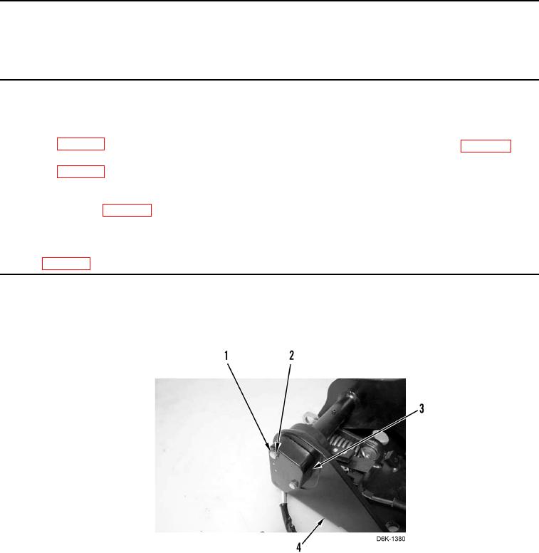
1. Remove two bolts (Figure 1, Item 1), washers (Figure 1, Item 2), and position sensor (Figure 1, Item 3) from
pedal support (Figure 1, Item 4).
Figure 1. Brake Pedal Position Sensor.
0243