
TM 5-2410-240-23-3
0242
INSTALLATION
000242
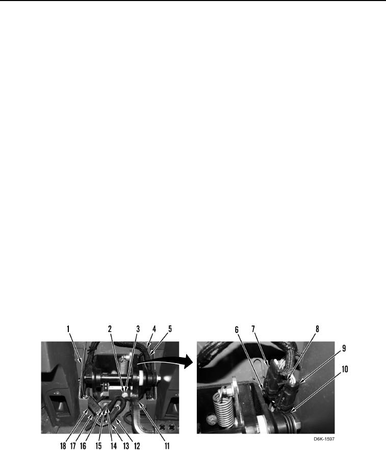
1. Install pedal assembly (Figure 24, Item 11), three washers (Figure 24, Item 2), and bolts (Figure 24, Item 3) on
cab (Figure 24, Item 1).
2. Position wiring harness (Figure 24, Item 5) on cab (Figure 24, Item 1).
3. Install three ground wires (Figure 24, Item 16), washers (Figure 24, Item 15), and bolt (Figure 24, Item 14) on
pedal assembly (Figure 24, Item 11).
N OT E
Install tiedown straps as noted during removal.
4. Install two new tiedown straps (Figure 24, Item 4) on wiring harness (Figure 24, Item 5).
N OT E
Install electrical connectors as tagged during removal.
5. Connect electrical connector (Figure 24, Item 12) on harness connector (Figure 24, Item 13).
6. Connect electrical connector (Figure 24, Item 18) on harness connector (Figure 24, Item 17).
7. Connect harness electrical connector (Figure 24, Item 10) on wiring harness connector (Figure 24, Item 9).
N OT E
Install tiedown strap as noted during removal.
8. Install new tiedown strap (Figure 24, Item 8) on wiring harness connectors (Figure 24, Items 10 and 9).
N OT E
Install electrical connector as tagged at removal.
9. Connect harness electrical connector (Figure 24, Item 6) on wiring harness connector (Figure 24, Item 7).
Figure 24. Lower Dash Cab Wiring Harness Connectors.
0242