
TM 5-2410-240-23-3
0242
ASSEMBLY CONTINUED
000242
WARN I N G
Springs may have significant spring tension, depending upon type or position of spring.
Use extreme caution when installing springs. Springs under tension can act as projectiles
when released and may result in severe injury to personnel.
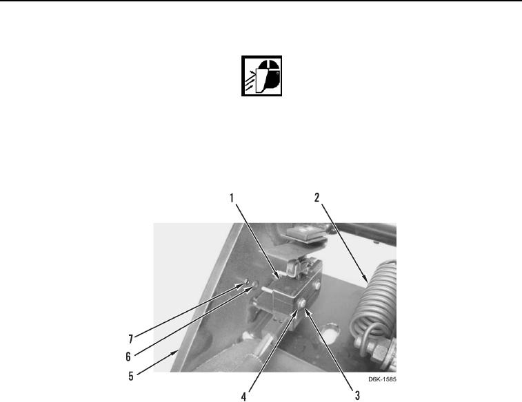
9. Install spring (Figure 19, Item 2), limit switch (Figure 19, Item 1), four washers (Figure 19, Items 6 and 4), two
bolts (Figure 19, Item 3), and nuts (Figure 19, Item 7) on pedal support (Figure 19, Item 5).
Figure 19. Brake Pedal Limit Switch and Spring.
0242