• Home
  • Download PDF
  • Order CD-ROM
  • Order in Print
Figure 10. Brake Pedal Plunger Assembly.
Figure 13. Brake Pedal Limit Switch Spring.

Field Maintenance Manual 3 D6K Dozer Type I With Winch and Type II With Ripper
Page Navigation
  715    716    717    718    719  720  721    722    723    724    725  
img
. .
TM 5-2410-240-23-3
0242
DISASSEMBLY CONTINUED
000242
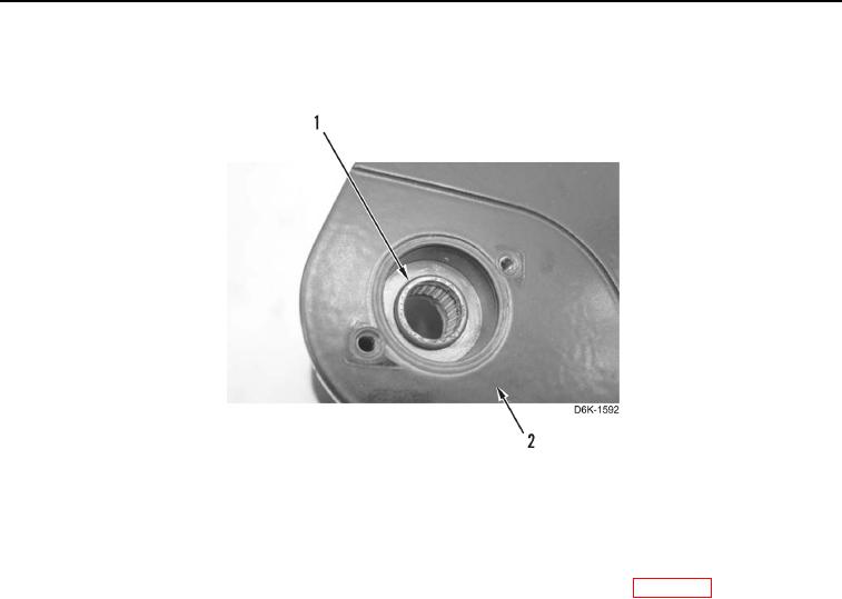
10. Remove two bearings (Figure 12, Item 1) from pedal support (Figure 12, Item 2).
Figure 12. Brake Pedal Bearings.
0242
END OF TASK
CLEANING AND INSPECTION
000242
Clean and inspect all components IAW Mechanical General Maintenance Instructions (WP 0282).
END OF TASK
ASSEMBLY
000242
1. Install two bearings (Figure 12, Item 1) on pedal support (Figure 12, Item 2).
0242-9


Privacy Statement
Press Release
Contact

© Copyright Integrated Publishing, Inc.. All Rights Reserved.