
TM 5-2410-240-23-3
0242
DISASSEMBLY CONTINUED
000242
N OT E
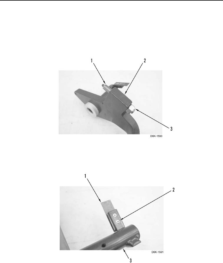
Measure length of plunger before removing from brake pedal.
8. Loosen nut (Figure 10, Item 3) and remove plunger (Figure 10, Item 1) and nut (Figure 10, Item 3) from brake
pedal (Figure 10, Item 2).
Figure 10. Brake Pedal Plunger Assembly.
0242
9. Remove two rivets (Figure 11, Item 2) and spring (Figure 11, Item 1) from brake pedal (Figure 11, Item 3).
Discard rivets.
Figure 11. Brake Pedal Limit Switch Spring.
0242