
TM 5-2410-240-23-3
0242
ASSEMBLY CONTINUED
000242
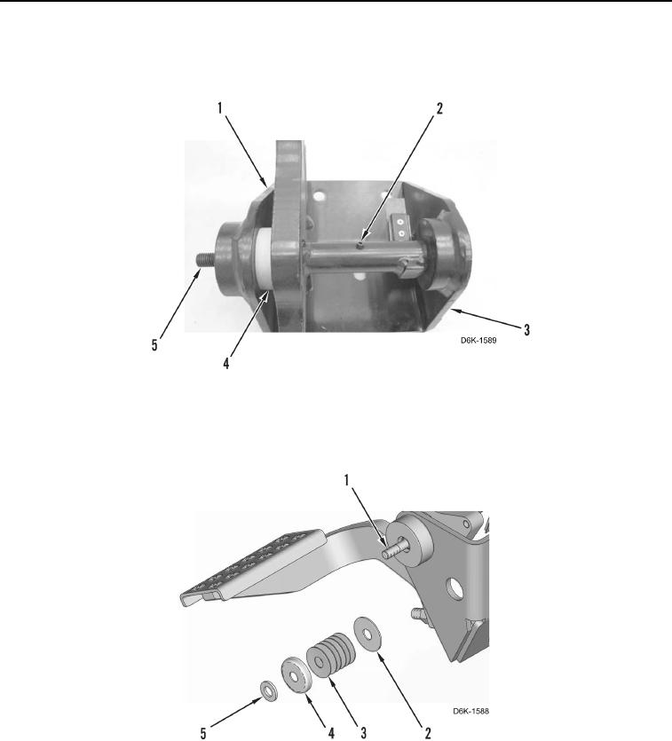
4. Install spacer (Figure 15, Item 4), pedal (Figure 15, Item 1), shaft (Figure 15, Item 5), and spring pin (Figure 15,
Item 2) on pedal support (Figure 15, Item 3).
Figure 15. Brake Pedal and Shaft.
0242
5. Install washer (Figure 16, Item 2), disc springs (Figure 16, Item 3), seat (Figure 16, Item 4), and washer
(Figure 16, Item 5) on shaft (Figure 16, Item 1).
Figure 16. Brake Pedal Shaft Components.
0242