
TM 5-2410-240-23-3
0242
DISASSEMBLY CONTINUED
000242
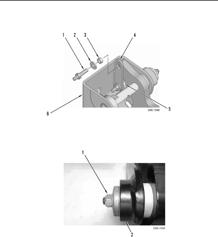
4. Remove two bolts (Figure 6, Item 1), nut (Figure 6, Item 5), three washers (Figure 6, Item 2), two spacers
(Figure 6, Item 3), and link (Figure 6, Item 4) from pedal support (Figure 6, Item 6).
Figure 6. Brake Pedal Link and Mounting Bolts.
0242
5. Remove locknut (Figure 7, Item 1) from pedal support (Figure 7, Item 2). Discard locknut.
Figure 7. Brake Pedal Shaft Locknut.
0242