
TM 5-2410-240-23-3
0242
ASSEMBLY CONTINUED
000242
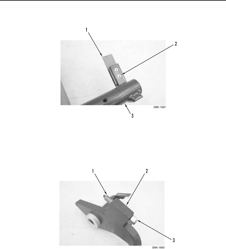
2. Install spring (Figure 13, Item 1) and two new rivets (Figure 13, Item 2) on brake pedal (Figure 13, Item 3).
Figure 13. Brake Pedal Limit Switch Spring.
0242
N OT E
Install plunger to length measured during removal.
3. Install plunger (Figure 14, Item 1) and nut (Figure 14, Item 3) on brake pedal (Figure 14, Item 2).
Figure 14. Brake Pedal Plunger Assembly.
0242