
TM 5-2410-240-23-3
0242
DISASSEMBLY CONTINUED
000242
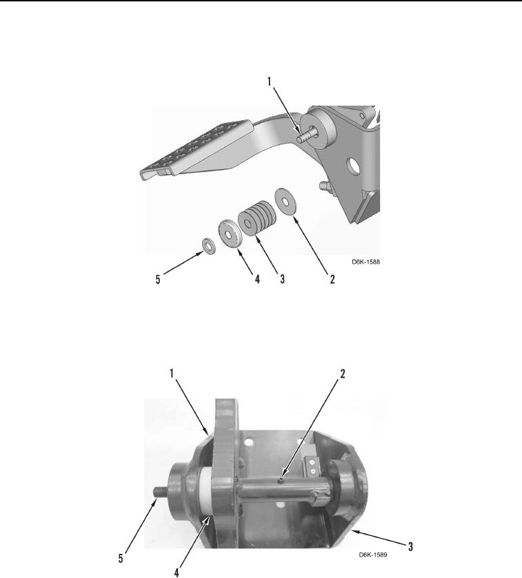
6. Remove washer (Figure 8, Item 5), seat (Figure 8, Item 4), disc springs (Figure 8, Item 3), and washer
(Figure 8, Item 2) from shaft (Figure 8, Item 1).
Figure 8. Brake Pedal Shaft Components.
0242
7. Remove spring pin (Figure 9, Item 2), shaft (Figure 9, Item 5), spacer (Figure 9, Item 4), and pedal
(Figure 9, Item 1) from pedal support (Figure 9, Item 3).
Figure 9. Brake Pedal and Shaft.
0242