• Home
  • Download PDF
  • Order CD-ROM
  • Order in Print
Figure 2. Lower Dash Cab Wiring Harness Connector.
Figure 5. Brake Pedal Limit Switch and Spring.

Field Maintenance Manual 3 D6K Dozer Type I With Winch and Type II With Ripper
Page Navigation
  710    711    712    713    714  715  716    717    718    719    720  
img
.
TM 5-2410-240-23-3
0242
DISASSEMBLY
000242
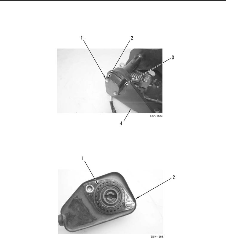
1. Remove two bolts (Figure 3, Item 1), washers (Figure 3, Item 2), and position sensor (Figure 3, Item 3) from
pedal support (Figure 3, Item 4).
Figure 3. Brake Pedal Position Sensor.
0242
2. Remove O-ring (Figure 4, Item 1) from position sensor (Figure 4, Item 2). Discard O-ring.
Figure 4. Position Sensor O-ring.
0242
0242-4


Privacy Statement
Press Release
Contact

© Copyright Integrated Publishing, Inc.. All Rights Reserved.