
TM 5-2410-240-23-3
0245
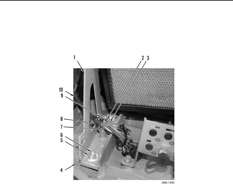
REMOVAL CONTINUED
2. Remove bolt (Figure 2, Item 9), washer (Figure 2, Item 2), clip (Figure 2, Item 8), bracket (Figure 2, Item 3),
and spacer (Figure 2, Item 7) from bracket (Figure 2, Item 1).
3. Position wiring harness (Figure 2, Item 10) aside.
4. Remove two bolts (Figure 2, Item 6), spacers (Figure 2, Item 5), and bracket (Figure 2, Item 1) from machine
(Figure 2, Item 4).
Figure 2. Bracket and Retaining Hardware Below A/C Heater Assembly.
0245