
TM 5-2410-240-23-3
0245
REMOVAL CONTINUED
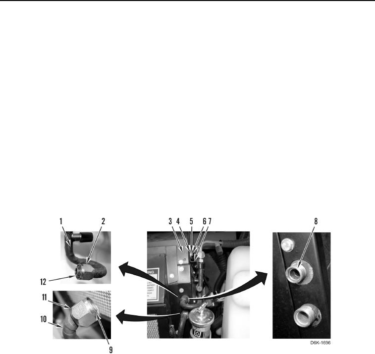
14. Remove bolt (Figure 5, Item 6), washer (Figure 5, Item 5), clip (Figure 5, Item 4), and bracket (Figure 5, Item 7)
from A/C heater assembly (Figure 5, Item 3).
C AU T I O N
Cap or plug all A/C lines and fittings during removal to protect against contamination.
Failure to follow this caution may result in equipment damage.
N OT E
Tag and mark A/C lines to aid installation.
15. Loosen fitting (Figure 5, Item 2) and disconnect orifice tube (Figure 5, Item 1) from evaporator core (Figure 5,
Item 8).
16. Remove O-ring (Figure 5, Item 12) from orifice tube (Figure 5, Item 1). Discard O-ring.
17. Loosen fitting (Figure 5, Item 11) and disconnect A/C line (Figure 5, Item 10) from evaporator core (Figure 5,
Item 8).
18. Remove O-ring (Figure 5, Item 9) from A/C line (Figure 5, Item 10). Discard O-ring.
19. Position orifice tube (Figure 5, Item 1) aside.
Figure 5. A/C Line, Orifice Tube, and O-rings on A/C Heater Assembly.
0245