
TM 5-2410-240-23-3
0245
REMOVAL CONTINUED
000245
N OT E
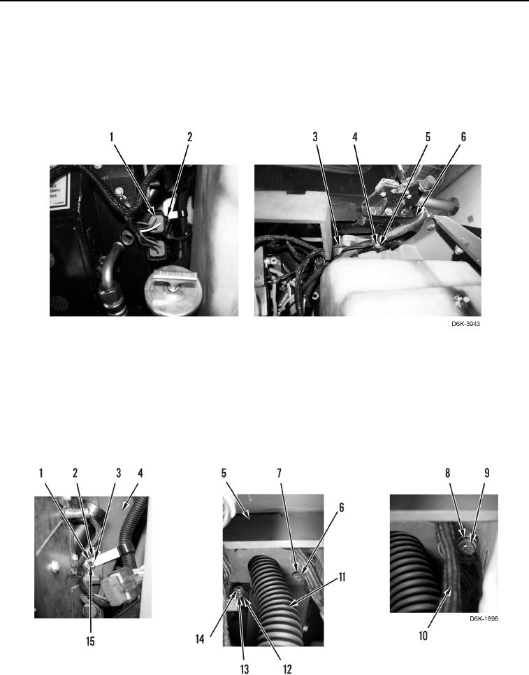
Tag wiring harness to aid installation.
22. Disconnect two wiring harnesses (Figure 7, Item 1) from two relays (Figure 7, Item 2)
23. Remove bolt (Figure 7, Item 5), washers (Figure 7, Item 4), and ground wire (Figure 7, Item 3) from cab
(Figure 7, Item 6).
Figure 7. Ground Wire.
0245
24. Remove bolt (Figure 8, Item 9) and three ground straps (Figure 8, Item 8) from machine (Figure 8, Item 4).
25. Remove two bolts (Figure 8, Item 6) and washers (Figure 8, Item 7) from bracket (Figure 8, Item 5).
26. Remove duct (Figure 8, Item 11) and wiring harness (Figure 8, Item 10) from bracket (Figure 8, Item 5) and
remove bracket from machine.
27. Remove nut (Figure 8, Item 13) and washer (Figure 8, Item 12) from stud (Figure 8, Item 14).
28. Remove nut (Figure 8, Item 1), washer (Figure 8, Item 3), and clamp (Figure 8, Item 2) from stud (Figure 8,
Item 15).
Figure 8. Bracket, Duct, Wiring Harness, and Retaining Hardware On and Above A/C Heater Assembly.
0245