
TM 5-2410-240-23-3
0245
REMOVAL CONTINUED
000245
WARN I N G
Engine coolant is very slippery. Immediately wipe up any spills. Failure to follow this
warning may result in injury to personnel.
N OT E
Tag and mark hose to aid installation.
Plug or cap hose and open port.
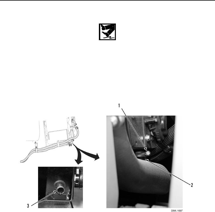
20. Loosen clamp (Figure 6, Item 1) and disconnect connector hose (Figure 6, Item 2) from heater core (Figure 6,
Item 3).
21. Remove clamp (Figure 6, Item 1) from connector hose (Figure 6, Item 2).
Figure 6. Connector Hose, Heater Core, and Clamp on Bottom of A/C Heater Assembly.
0245