
TM 5-2410-240-23-3
0248
A/C HOSE INSTALLATION CONTINUED
000248
N OT E
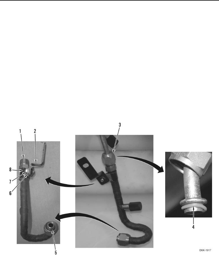
Install clamp and bracket as noted during removal.
29. Install clamp (Figure 21, Item 8) on orifice tube (Figure 21, Item 1).
30. Install bracket (Figure 21, Item 2), washer (Figure 21, Item 6), and bolt (Figure 21, Item 7) on clamp (Figure 21,
Item 8).
N OT E
Remove caps or plugs from A/C hose and orifice tube and install A/C hose as noted
during removal.
31. Install new O-ring (Figure 21, Item 5) on orifice tube (Figure 21, Item 1) and apply refrigerant compressor
lubricating oil on O-ring.
32. Install new O-ring (Figure 21, Item 4) on A/C hose (Figure 21, Item 3) and apply refrigerant compressor
lubricating oil on O-ring.
33. Loosely connect A/C hose (Figure 21, Item 3) on orifice tube (Figure 21, Item 1).
Figure 21. Orifice Tube, O-ring, and Retaining Hardware.
0248