
TM 5-2410-240-23-3
0248
A/C HOSE INSTALLATION CONTINUED
000248
N OT E
Remove caps or plugs from A/C hoses and fittings.
Install A/C hoses and fittings as noted during removal.
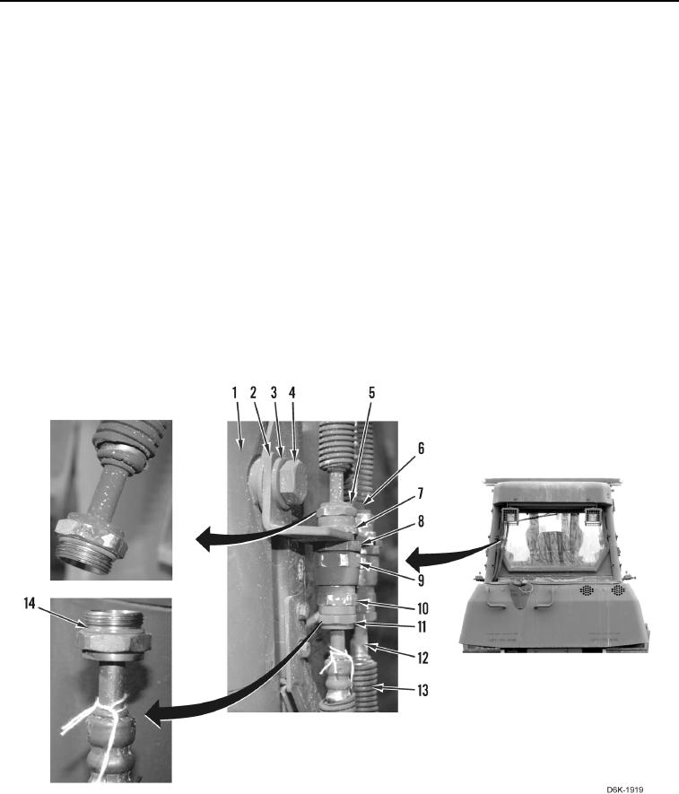
18. Install bracket (Figure 19, Item 2), washer (Figure 19, Item 3), and bolt (Figure 19, Item 4) on machine
(Figure 19, Item 1).
19. Install two new O-rings (Figure 19 Item 14) on A/C hoses (Figure 19, Items 5 and 6) and apply refrigerant
compressor lubricating oil on O-rings.
20. Install two fittings (Figure 19, Item 7) on A/C hoses (Figure 19, Items 5 and 6).
21. Install two fittings (Figure 19, Item 7) and nuts (Figure 19, Item 8) on bracket (Figure 19, Item 2).
22. Install two convoluted tubes (Figure 19, Item 13) on A/C hoses (Figure 19, Items 11 and 12).
23. Install two A/C hoses (Figure 19, Items 11 and 12) on machine (Figure 19, Item 1).
24. Install two new O-rings (Figure 19, Item 14) on A/C hoses (Figure 19, Items 11 and 12) and apply refrigerant
compressor lubricating oil on O-rings.
25. Install two fittings (Figure 19, Item 10) on A/C hoses (Figure 19, Items 11 and 12).
26. Install two fittings (Figure 19, Item 9) on fittings (Figure 19, Item 7).
Figure 19. A/C Hoses, Fittings and Bracket on Rear of Machine.
0248