
TM 5-2410-240-23-3
0248
A/C BRACKET REMOVAL CONTINUED
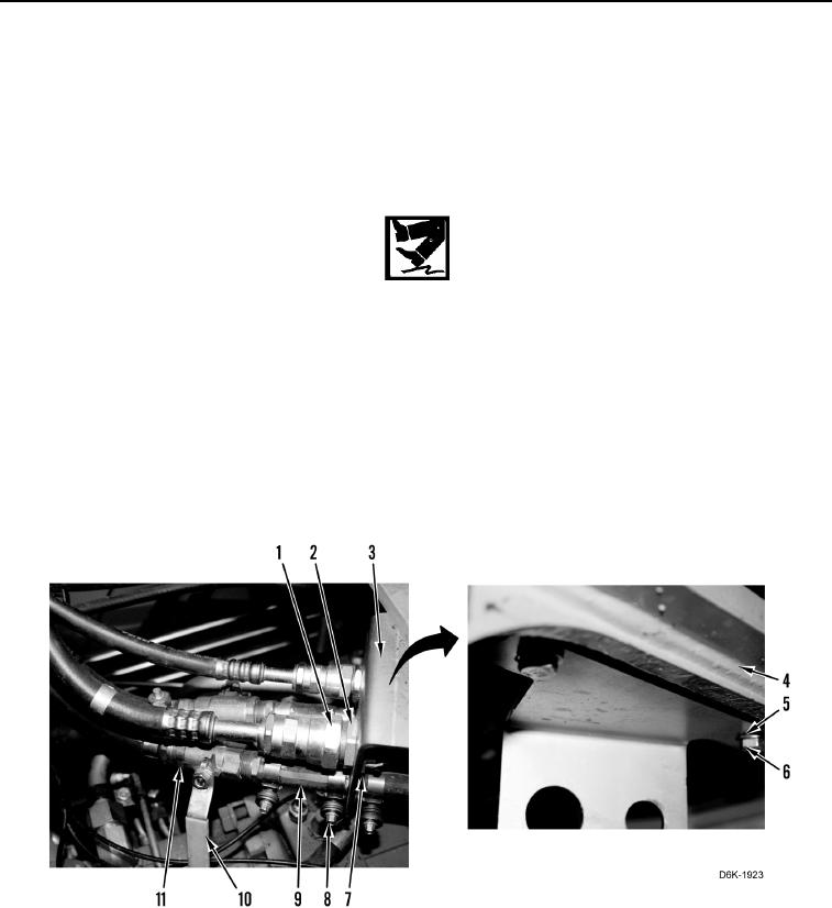
2. Loosen two fittings (Figure 15, Item 1).
3. Remove two fittings (Figure 15, Item 1) from fittings (Figure 15, Item 7) and position aside.
4. Remove two nuts (Figure 15, Item 2) and fittings (Figure 15, Item 7) from bracket (Figure 15, Item 3) and
position aside.
5. Turn two handles (Figure 15, Item 10) on shutoff valves (Figure 15, Item 11) to OFF position.
WARN I N G
Engine coolant is very slippery. Immediately wipe up any spills. Failure to follow this
warning may result in injury to personnel.
N OT E
Tag heater hoses to aid installation.
Cap or plug heater hoses and fittings.
6. Loosen four clamps (Figure 15, Item 8) and disconnect heater hoses (Figure 15, Item 9) from bracket
(Figure 15, Item 3) and position aside.
7. Remove two bolts (Figure 15, Item 6), washers (Figure 15, Item 5), and bracket (Figure 15, Item 3) from
machine (Figure 15, Item 4).
Figure 15. A/C Hoses, Fittings, Heater Hoses, and Bracket Underneath Front Cab Floor Plates.
0248
END OF TASK