
TM 5-2410-240-23-3
0259
INSTALLATION
000259
Remove caps and plugs before instaling hydraulic and lubrication hoses.
l
Install hydraulic and lubrication hoses as noted during removal.
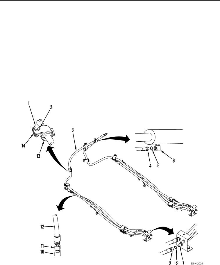
1. Install two lubrication hoses (Figure 2, Item 12) on machine.
2. Connect two lubrication hoses (Figure 2, Item 12) to connectors (Figure 2, Item 10) and tighten fittings
(Figure 2, Item 11).
3. Install three new O-rings (Figure 2, Item 8) on connectors (Figure 2, Item 7).
4. Connect three hydraulic hoses (Figure 2, Item 3) to connectors (Figure 2, Item 7) and tighten fittings (Figure 2,
Item 9).
5. Install three new O-rings (Figure 2, Item 5) on connectors (Figure 2, Item 6).
6. Connect three hydraulic hoses (Figure 2, Item 3) to connectors (Figure 2, Item 6) and tighten fittings (Figure 2,
Item 4).
7. Install four grommets (Figure 2, Item 13), five clamps (Figure 2, Item 14), four washers (Figure 2, Item 2), and
bolts (Figure 2, Item 1) on three hydraulic hoses (Figure 1, Item 3).
Figure 2. Hydraulic and Lubrication Hoses.
0259
END OF TASK