
TM 5-2410-240-23-3
0260
REMOVAL CONTINUED
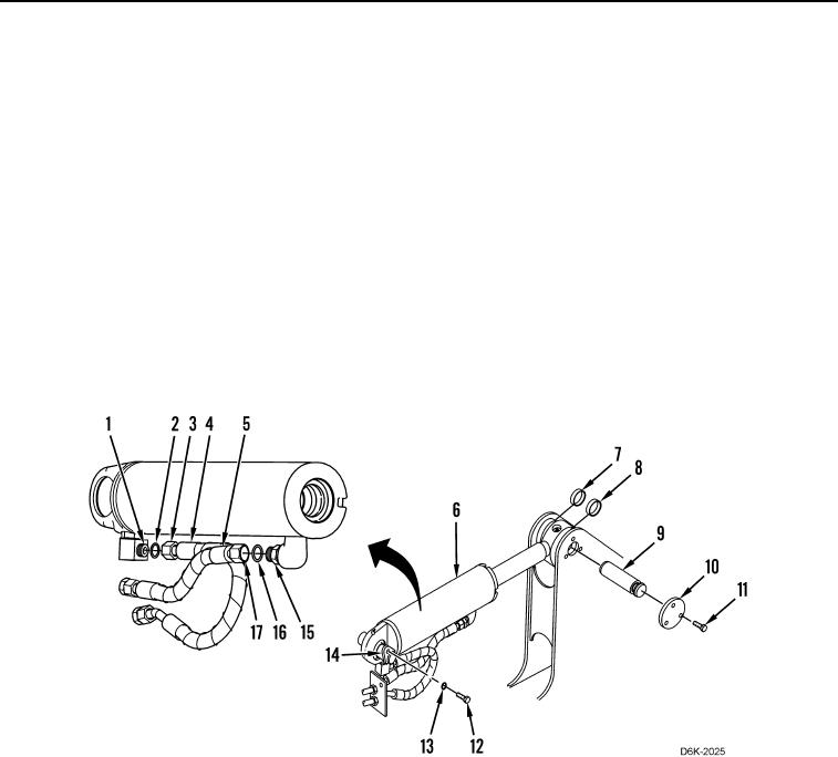
1. Attach sling and lifting device on lift cylinder (Figure 1, Item 6).
2. Loosen two fittings (Figure 1, Items 3 and 17) and disconnect hydraulic hoses (Figure 1, Items 4 and 5) from
connectors (Figure 1, Items 1 and 15). Position hydraulic hoses aside.
3. Remove two O-rings (Figure 1, Items 2 and 16) from connectors (Figure 1, Items 1 and 15). Discard O-rings.
N OT E
Note position and orientation of spacers to aid installation.
4. Remove three bolts (Figure 1, Item 11), retainer (Figure 1, Item 10), pin (Figure 1, Item 9), and spacers
(Figure 1, Items 7 and 8), retaining lift cylinder (Figure 1, Item 6) on machine.
5. Remove bolt (Figure 1, Item 12), washer (Figure 1, Item 13), and pin (Figure 1, Item 14), retaining lift cylinder
(Figure 1, Item 6) on machine.
6. Using lifting device and assistance, remove lift cylinder (Figure 1, Item 6) from machine.
7. Place lift cylinder (Figure 1, Item 6) on flat surface and remove sling and lifting device.
Figure 1. Fine Grading Hoses, Lift Cylinder, and Retaining Hardware.
0260
END OF TASK