
TM 5-2410-240-23-3
0264
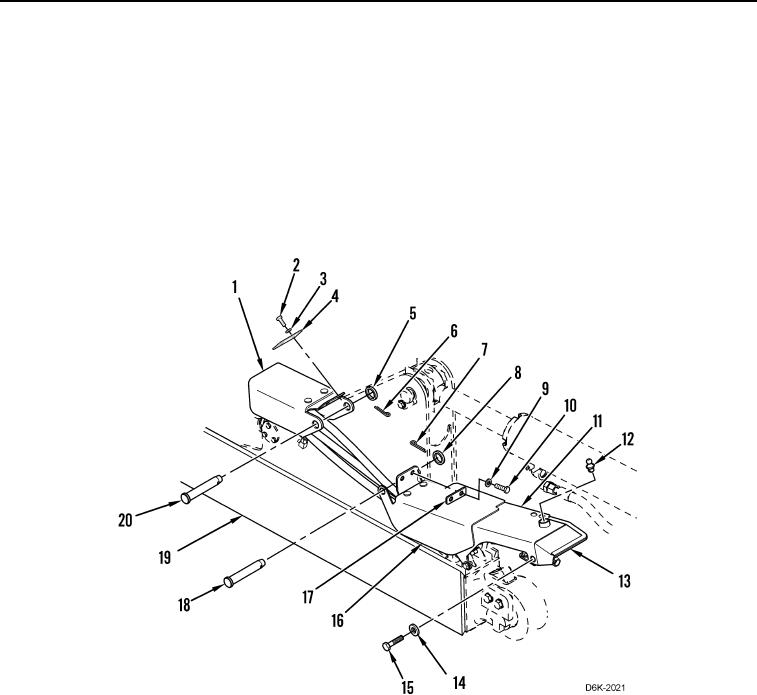
CYLINDER AND HOSE DEBRIS GUARD AND BRACKET REMOVAL CONTINUED
8. Remove cotter pin (Figure 3, Item 6), washer (Figure 3, Item 5), pin (Figure 3, Item 20), two bolts (Figure 3,
Item 2), washers (Figure 3, Item 3), spacer (Figure 3, Item 4), and guard (Figure 3, Item 1) from frame
(Figure 3, Item 19). Discard cotter pin.
9. Remove cotter pin (Figure 3, Item 7), washer (Figure 3, Item 8), pin (Figure 3, Item 18), two bolts (Figure 3,
Item 10), washers (Figure 3, Item 9), spacer (Figure 3, Item 17), and guard (Figure 3, Item 16) from frame
(Figure 3, Item 19). Discard cotter pin.
10. Remove two bolts (Figure 3, Item 15) and washers (Figure 3, Item 14) retaining bracket (Figure 3, Item 11) on
machine.
11. Remove grease fitting (Figure 3, Item 12) and seal (Figure 3, Item 13) from bracket (Figure 3, Item 11).
Figure 3. Guards, Bracket, and Retaining Hardware.
0264