
TM 5-2410-240-23-3
0263
REMOVAL
000263
1. Turn battery disconnect switch ON (TM 5-2410-240-10).
2. Start engine (TM 5-2410-240-10).
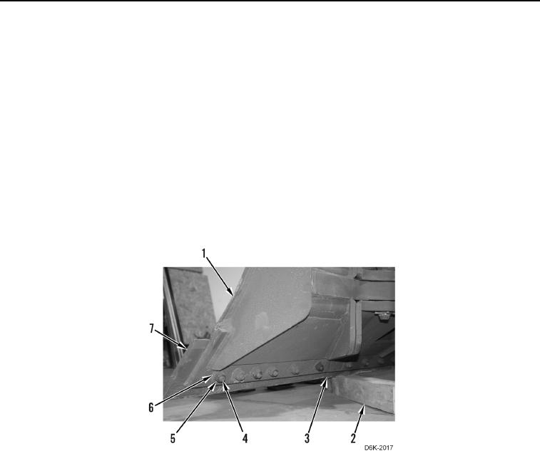
3. Raise blade (Figure 1, Item 1) (TM 5-2410-240-10).
4. Have assistant position wood block (Figure 1, Item 2) underneath two cutting edges (Figure 1, Item 3) when
replacing bit ends (Figure 1, Item 7), or underneath two bit ends when replacing cutting edges.
5. Lower blade (Figure 1, Item 1) (TM 5-2410-240-10) on supports (Figure 1, Item 2).
6. Shut engine OFF (TM 5-2410-240-10).
7. Turn battery disconnect switch OFF (TM 5-2410-240-10).
8. When replacing 2 bit ends (Figure 1, Item 7), remove 10 nuts (Figure 1, Item 5), washers (Figure 1, Item 6),
bolts (Figure 1, Item 4), and 2 bit ends from blade (Figure 1, Item 1).
9. When replacing 2 cutting edges (Figure 1, Item 3), remove 12 nuts (Figure 1, Item 5), washers (Figure 1, Item
6), bolts (Figure 1, Item 4), and 2 cutting edges from blade (Figure 1, Item 1).
Figure 1. Blade, Cutting Edges, Bit Ends, and Retaining Hardware.
0263
END OF TASK