
TM 5-2410-240-23-3
0262
INSTALLATION CONTINUED
N OT E
Remove caps and plugs beforeinstalling hydraulic hose.
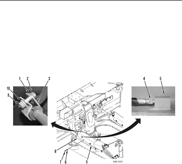
Install hydraulic hoses as noted during removal.
11. Install bracket (Figure 10, Item 5) on machine.
12. Connect hose (Figure 10, Item 4) to bracket (Figure 10, Item 5).
13. Install bracket (Figure 10, Item 5) on angle cylinder (Figure 10, Item 8).
14. Install clamp (Figure 10, Item 3), washer (Figure 10, Item 1), bolt (Figure 10, Item 2), washer (Figure 10,
Item 10), and nut (Figure 10, Item 9) on bracket (Figure 10, Item 5).
15. Install four washers (Figure 10, Item 6) and bolts (Figure 10, Item 7) retaining bracket (Figure 10, Item 5) on
angle cylinder (Figure 10, Item 8).
Figure 10. Angle Cylinder, Bracket, Lubrication Hose, and Retaining Hardware.
0262
END OF TASK
FOLLOW-ON TASKS
000262
1. Check hydraulic oil level (WP 0160).
2. Verify correct operation of machine (TM 5-2410-240-10).
END OF TASK
END OF WORK PACKAGE