
TM 5-2410-240-23-3
0262
INSTALLATION
000262
WARN I N G
Use extreme caution when handling heavy parts. Provide adequate support and use
assistance during procedure. Ensure any lifting device used is in good condition and of
suitable load capacity. Keep clear of heavy parts supported only by lifting device. Failure to
follow this warning may result in injury or death to personnel.
N OT E
Angle cylinder weighs approximately 100 lb (45 kg).
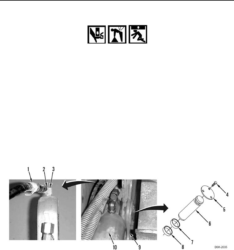
1. Install lifting device on angle cylinder (Figure 7, Item 10).
2. Connect lubrication hose (Figure 7, Item 1) to connector (Figure 7, Item 3) and tighten fitting (Figure 7, Item 2).
3. Using lifting device and assistance, install angle cylinder (Figure 7, Item 10) on machine.
4. Apply grease on pin (Figure 7, Item 6) and bore of angle cylinder (Figure 7, Item 10).
N OT E
Install spacers as noted during removal.
5. Install two spacers (Figure 7, Items 8 and 7), pin (Figure 7, Item 6), retainer (Figure 7, Item 5), and three bolts
(Figure 7, Item 4), retaining angle cylinder (Figure 7, Item 10) on frame (Figure 7, Item 9).
Figure 7. Angle Cylinder, Retaining Hardware, and Lubrication Hose.
0262