
TM 5-2410-240-23-3
0263
CLEANING AND INSPECTION
000263
C AU T I O N
All surfaces that contact bolts must be free of paint, rust, nicks, and burrs. Failure to follow
this caution may result in equipment damage.
Clean and inspect all parts IAW Mechanical General Maintenance Instructions (WP 0282).
END OF TASK
INSTALLATION
000263
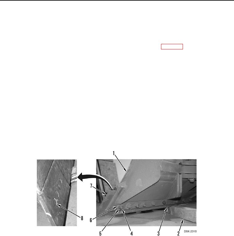
1. When replacing 2 cutting edges (Figure 2, Item 3), install 2 cutting edges, 12 bolts (Figure 2, Item 4), washers
(Figure 2, Item 6), and nuts (Figure 2, Item 5) on blade (Figure 2, Item 1).
2. When replacing 2 bit ends (Figure 2, Item 7), install 10 bolts (Figure 2, Item 4), washers (Figure 2, Item 6), and
nuts (Figure 2, Item 5) on blade (Figure 2, Item 1).
3. Tighten 12 nuts (Figure 2, Item 5) for 2 cutting edges (Figure 2, Item 3) or 10 nuts for 2 bit ends (Figure 2,
Item 7) to 350 45 lb-ft (475 60 Nm).
4. Forcefully strike 12 bolt heads (Figure 2, Item 8) for 2 cutting edges (Figure 2, Item 3) or 10 bolt heads for 2 bit
ends (Figure 2, Item 7) with a hammer and punch.
5. Retighten 12 nuts (Figure 2, Item 5) for 2 cutting edges (Figure 2, Item 3) or 10 nuts for 2 bit ends (Figure 2,
Item 7) to 350 45 lb-ft (475 60 Nm).
6. Raise blade (Figure 2, Item 1) and remove supports (Figure 2, Item 2).
Figure 2. Blade, Cutting Edges, Bit Ends, and Retaining Hardware.
0263
END OF TASK
FOLLOW-ON TASKS
000263
Verify correct operation of machine (TM 5-2410-240-10).
END OF TASK
END OF WORK PACKAGE
0263-3/(4 blank)