
TM 5-2410-240-23-3
0262
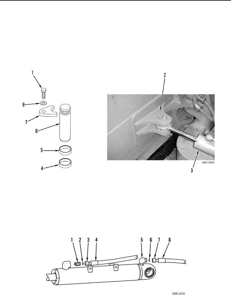
INSTALLATION CONTINUED
6. Apply grease on pin (Figure 8, Item 6).
N OT E
Install spacers as noted during removal.
7. Install two spacers (Figure 8, Items 4 and 5), pin (Figure 8, Item 6), retainer (Figure 8, Item 7), washer
(Figure 8, Item 8), and bolt (Figure 8, Item 1), retaining angle cylinder (Figure 8, Item 3) on blade (Figure 8,
Item 2).
8. Remove lifting device from angle cylinder (Figure 8, Item 3).
Figure 8. Angle Cylinder Retaining Hardware on Blade.
0262
N OT E
Remove caps and plugs beforeinstalling hydraulic hose.
Install hydraulic hoses as noted during removal.
9. Install two new O-rings (Figure 9, Items 6 and 2) on connectors (Figure 9, Items 5 and 1).
10. Connect two hydraulic hoses (Figure 9, Items 8 and 4) to connectors (Figure 9, Items 5 and 1) and tighten
fittings (Figure 9, Items 7 and 3).
Figure 9. Hydraulic Hoses.
0262