
TM 5-2410-240-23-3
0264
CYLINDER AND HOSE DEBRIS GUARD AND BRACKET REMOVAL
000264
N OT E
This procedure covers the removal of cylinder and hose debris guards and brackets from
one side of machine. Follow the same procedure when removing cylinder and hose debris
guards and brackets from other side of machine.
Care must be taken to ensure that fluidsare contained during performance of inspection,
maintenance, testing, adjusting, and repair of machine. Be prepared to collect fluid with
suitable containers before opening any compartment or disassembling any component
containing fluids.
Tag and identify all hoses and lines to aid installation.
Cap or plug all open lines and ports to prevent contaminants from entering system.
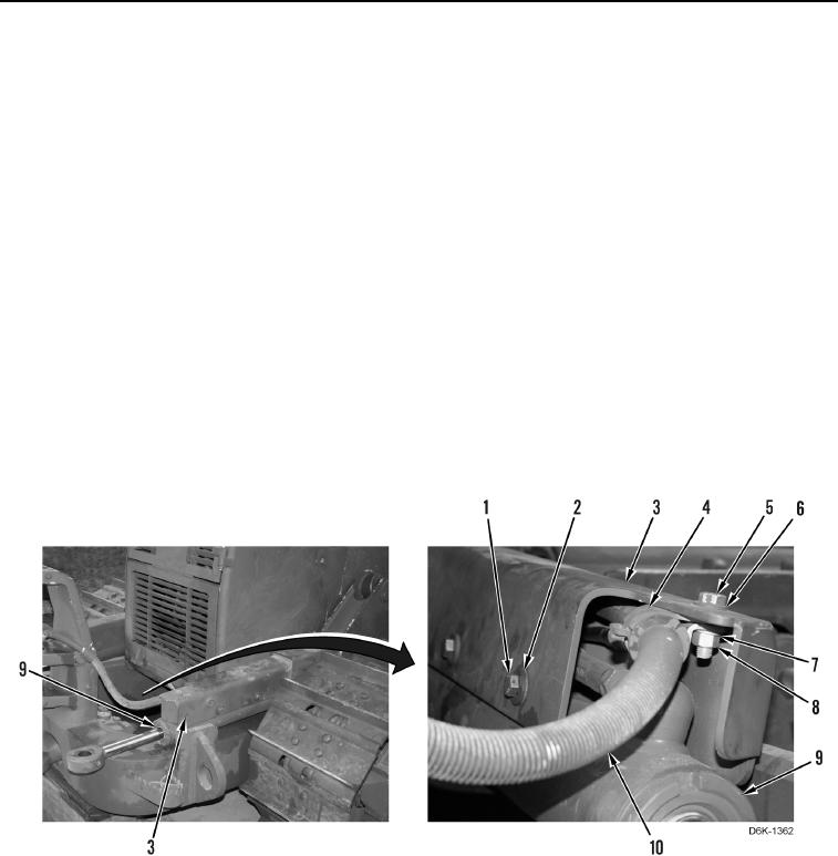
1. Remove four bolts (Figure 1, Item 1) and washers (Figure 1, Item 2) retaining bracket (Figure 1, Item 3) on
angle cylinder (Figure 1, Item 9).
2. Remove nut (Figure 1, Item 8), washer (Figure 1, Item 7), bolt (Figure 1, Item 5), washer (Figure 1, Item 6), and
clamp (Figure 1, Item 4) from bracket (Figure 1, Item 3).
3. Remove bracket (Figure 1, Item 4) from hose (Figure 1, Item 10).
4. Remove bracket (Figure 1, Item 3) from angle cylinder (Figure 1, Item 9) and position upside down on
machine.
Figure 1. Tilt Cylinder, Guard, Angle Cylinder, Bracket, and Retaining Hardware.
0264