
TM 5-2410-240-23-3
0284
PREPARING POWERTRAIN FOR AIRDROP
000284
N OT E
Two load support pads are located on brackets above center belly plates. To protect
powertrain from damage resulting from airdrop, all two load support pads must be
tightened against powertrain using load support kit T-bolts (TM 5-2410-240-10). T-bolts
are located in BII tool box.
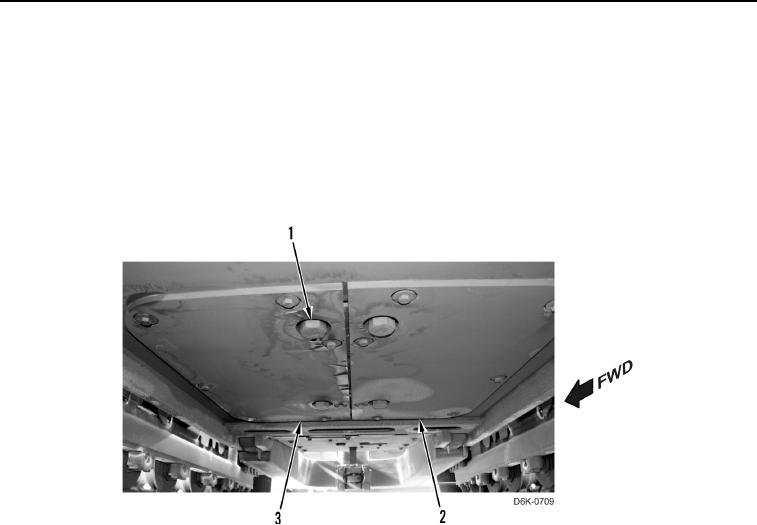
1. Remove four large bolts (Figure 33, Item 1) from center belly plates (Figure 33, Items 2 and 3).
Figure 33. Bolt Removal - Center Belly Plates.
0284