
TM 5-2410-240-23-3
0284
PREPARING POWERTRAIN FOR AIRDROP CONTINUED
N OT E
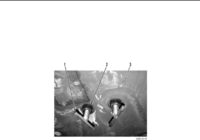
To prepare load support kit T-bolts for installation, remove nut and washer. Re-install nut,
threading it toward T-bolt handle. Re-install washer on T-bolt to ensure it is between nut
and belly plate when installed.
2. Install four load support kit T-bolts (Figure 34, Item 1) with washers (Figure 34, Item 2) on belly plates
(Figure 34, Item 3).
Figure 34. Installing Load Support T-bolts.
0284