
TM 5-2410-241-23-1
0005
AIR INLET AND EXHAUST SYSTEM CONTINUED
Valves and Valve System Components
0005
The valve system components control the flow of inlet air into the cylinders and exhaust gases out of the cylinders
during engine operation.
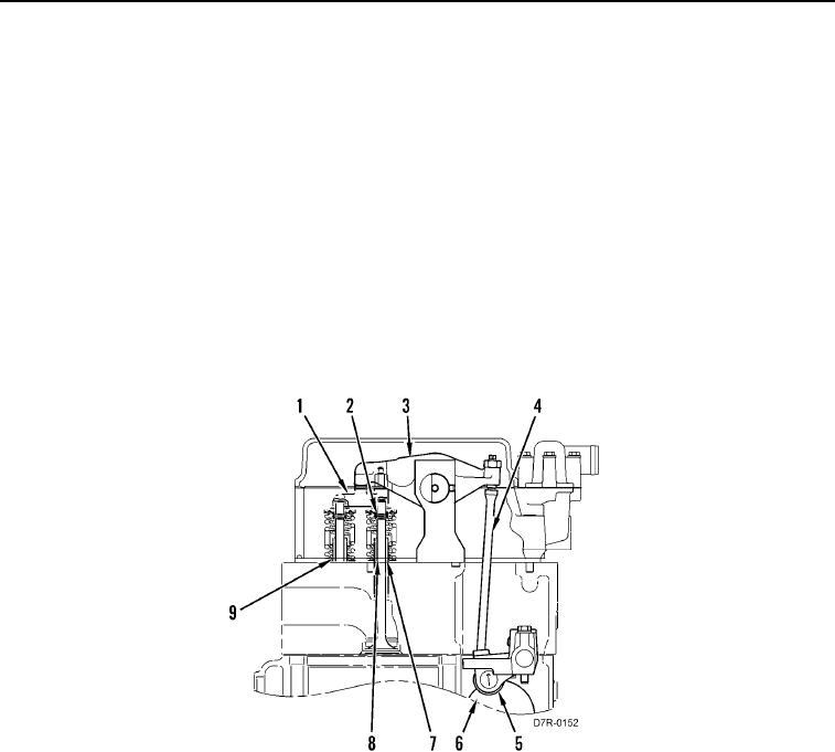
The crankshaft gear drives the camshaft gear through an idler gear. Camshaft (Figure 3, Item 6) must be timed to
the crankshaft in order to get the correct relation between the piston movement and the valve movement.
The camshaft has three camshaft lobes for each cylinder. Two lobes operate the inlet and exhaust valves, and one
operates the unit injector mechanism. As the camshaft turns, the camshaft lobes cause a lifter (Figure 3, Item 5) to
move a pushrod (Figure 3, Item 4) up and down. Upward movement of the pushrod against the rocker arm
(Figure 3, Item 3) results in downward movement of bridge (Figure 3, Item 1) and opening of the valves (Figure 3,
Item 8).
Each cylinder has two inlet valves, two exhaust valves, and four valve guides (Figure 3, Item 7). Valve springs
(Figure 3, Item 9) close the valves when the lifters move downward. Valve rotators (Figure 3, Item 2) cause the
valves to rotate while the engine is running. The rotation of the valves keeps the carbon deposits on the valves to a
minimum. Also, the rotation gives the valves longer service life.
Figure 3. Valve System Components.
0005
END OF WORK PACKAGE