TM 5-2410-241-23-1
0006
LUBRICATION SYSTEM CONTINUED
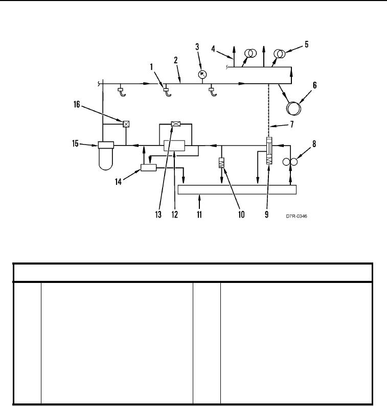
Figure 1. Lubrication System Schematic.
0006
Table 1. Lubrication System.
0006
Key Component
1
Piston cooling jets
9
Oil pump bypass valve
2
Main oil gallery in cylinder block
10
High pressure relief valve
3
Engine oil pressure sensor
11
Oil pan sump
4
Oil flow to valve mechanism
12
Engine oil cooler
5
Camshaft journals
13
Oil cooler bypass valve
6
Main bearings
14
Bypass housing
7
Signal line
15
Engine oil filter
8
Engine oil pump
16
Oil filter bypass valve

