
TM 5-2410-241-23-1
0008
ELECTRICAL SYSTEM CONTINUED
Service Brake Pedal Switch
0008
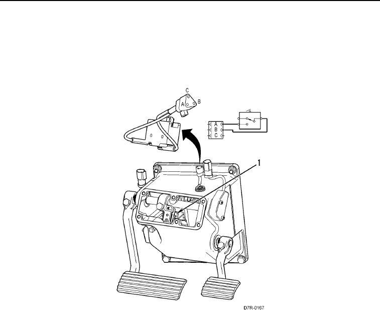
The service brake pedal switch (Figure 11, Item 1) is used to activate the secondary brake. The N/O contacts for
the switch are connected to a + battery wire and the wire for the secondary brake dump solenoid. When the service
brake pedal is fully depressed, the N/O contacts of the switch will close. This will allow the + battery power to
energize the secondary brake dump solenoid.
Figure 11. Service Brake Pedal Switch.
0008
The ECM monitors the secondary brake circuit. If the ECM detects an abnormal condition in the circuit, it will log a
diagnostic code for the solenoid valve.