
TM 5-2410-241-23-1
0008
ELECTRICAL SYSTEM CONTINUED
Sensors
0008
Sensors provide information to the ECM about changing conditions. Some types of information are about speed or
position. The signal changes in a proportional manner in order to reflect the changing condition. The types of
signals that are recognized by the ECM are listed below:
Frequency (Hz) The sensor produces a signal that varies the frequency as the condition changes.
Pulse width modulation (PWM) The sensor produces a signal that varies the duty cycle as the condition
changes. The duty cycle is the percentage of time that the square wave PWM signal is "Hi" compared to the time
that the signal is "Low." The frequency of this signal is constant.
Speed Sensor (Torque Converter Output)
0008
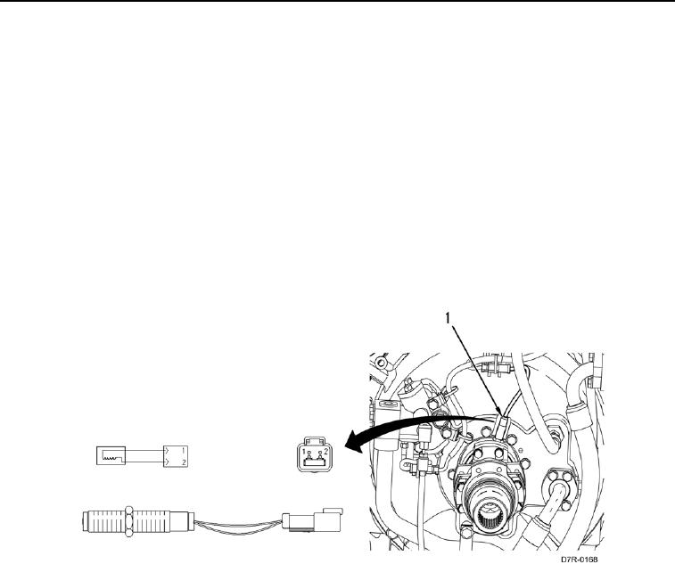
The torque converter output speed sensor (Figure 12, Item 1) is a frequency sensor, which produces a signal that
varies the frequency (Hz) as the condition changes. The sensor generates a frequency by passing a metallic object
such as the tooth of a gear in front of the sensor. The ECM measures the frequency and determines the speed of
the component. The speed sensor has two input connections to the ECM ("+" and "-").
Figure 12. Speed Sensor Torque Converter Output.
0008