
TM 5-2410-241-23-1
0009
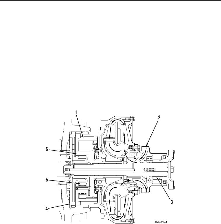
PRIMARY POWERTRAIN CONTINUED
As the speed of the ring gear (Figure 9, Item 1) decreases, the torque of the engine is multiplied through the sun
gear (Figure 9, Item 4) and through the planetary gear set. The torque multiplication is sent to the planetary carrier
(Figure 9, Item 6) and to the output shaft (Figure 9, Item 3).
When the machine operates under higher load, the resistance to rotation of the planetary carrier (Figure 9, Item 6)
increases and the speed of the ring gear decreases. The slower speed allows higher torque multiplication through
the torque converter turbine and through the sun gear.
If the resistance to rotation of the planetary carrier becomes high enough, the ring gear stops. During some very
high load conditions, the rotation of the planetary carrier and the rotation of the output shaft also stop. The stopped
output shaft causes the ring gear to turn slowly in the opposite direction. The torque multiplication of the torque
converter turbine and the sun gear is at the maximum.
Torque Divider Lubrication
0009
Lubrication oil for the torque divider bearings and for the planetary gears (Figure 9, Item 5) comes from the supply
(Figure 9, Item 2) to the torque converter. The bearings constantly run in oil. Bearings and gears in the planetary
gear set and the pilot bearings receive lubrication through passages in the output shaft.
Figure 9. Torque Divider.
0009