
TM 5-2410-241-23-1
0009
PRIMARY POWERTRAIN CONTINUED
Relief Valve (Torque Converter Inlet) (Lubrication Distribution Manifold)
0009
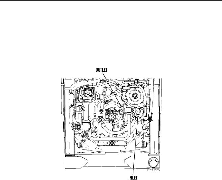
The torque converter inlet relief valve (Figure 10) is part of the lubrication distribution manifold. The torque
converter inlet relief valve limits the maximum oil pressure to the torque converter. The purpose of inlet relief valve
is to prevent damage to the torque converter when the engine is started and the oil is cold.
Relief Valve (Torque Converter Outlet)
0009
The outlet relief valve for the torque converter is fastened to the torque divider case and maintains pressure in the
torque converter.
Figure 10. Relief Valve (Torque Converter Inlet and Outlet).
0009