TM 5-2410-241-23-1
0009
PRIMARY POWERTRAIN CONTINUED
Transmission
0009
The transmission has five hydraulically activated clutches. Combinations of the clutches allow the transmission to
provide three speeds FORWARD and three speeds REVERSE (Table 1). The speed and direction are
electronically controlled.
The five transmission clutches are disc types and are in separate housings.
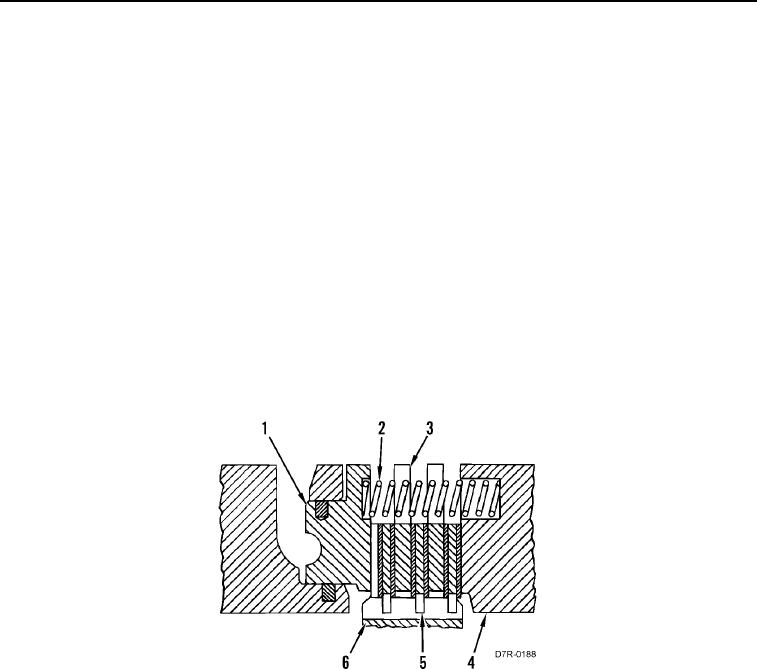
Each clutch has friction discs (Figure 11, Item 5) and clutch plates (Figure 11, Item 3). The inside teeth of the
friction discs (Figure 11, Item 5) are engaged with the outside teeth of ring gear (Figure 11, Item 6). Notches on the
outside diameter of the clutch plates (Figure 11, Item 3) are engaged with pins in the clutch housing. The pins
prevent the rotation of the clutch plates.
The spring (Figure 11, Item 2) is located between the clutch housing (Figure 11, Item 4) and the piston (Figure 11,
Item 1). The spring is in compression.
When the pressure of the oil in the area behind the piston increases, the piston moves to the right against the force
of the spring (Figure 11, Item 2), pushing the friction discs and clutch plates together. The clutch is now engaged.
The friction discs keep the ring gear (Figure 11, Item 6) from rotation.
The clutch is released when the pressure in the area behind piston (Figure 11, Item 1) decreases and the force of
the spring (Figure 11, Item 2) moves the piston to the left. The friction discs and clutch plates now move apart and
the clutch is no longer engaged.
Figure 11. Clutch Operation (Typical Example).
0009

