
TM 5-2410-241-23-1
0009
PRIMARY POWERTRAIN CONTINUED
Transfer and Bevel Gears
0009
The transfer and bevel gears are located in the transfer case. The transfer case is attached to the transmission
case. The transfer and bevel gears transfer mechanical power from the transmission through the brakes to the final
drive.
A drive shaft connects the yoke on the torque converter to the yoke on the transfer case. The yoke on the transfer
case is connected to the transmission input shaft (Figure 15, Item 4) by splines.
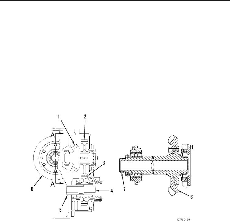
When a speed clutch and a direction clutch are engaged, power is sent from the planetary transmission to the
transmission output shaft (Figure 15, Item 5). Then, the power is sent to the transfer gear (Figure 15, Item 3).
The transfer gear (Figure 15, Item 3) turns the transfer gear (Figure 15, Item 2). The transfer gear (Figure 15,
Item 2) is connected to the pinion (Figure 15, Item 1) by splines. The pinion (Figure 15, Item 1) turns the bevel gear
(Figure 15, Item 6), which is fastened to the bevel gear shaft (Figure 15, Item 7) by bolts. The inner axle shafts
send power to the brakes.
The bevel gear, the pinion, and the transfer gears are lubricated with oil from the powertrain oil system. Oil flows
through passages in the transfer case and through a tube in the bevel gear case. Oil from the tube lubricates the
gears by spray lubrication.
Figure 15. Transfer and Bevel Gears.
0009
Brake Control Valve
0009
The brake control valve is installed on top of the case above the left front side and is operated electrically by the
ECM. The ECM responds to the operator's movement of the service brake pedal.
The service brake pedal modulates the engagement of both of the brakes in order to stop the machine. The
parking brake switch engages both of the brakes to prevent movement of the machine.
The brakes are engaged with spring force. Hydraulic pressure is required to disengage the brakes. If hydraulic
pressure is lost, the brakes fully engage due to the action of the spring force.
The brake control valve includes a valve body and a manifold. The valve contains a separate manifold for the
service brakes. The valve also contains parking or secondary valves for the brakes. One pilot valve is used for both
brakes. Proportional valve, accumulator piston, and reducing spool are used to operate the pilot valve.