
TM 5-2410-241-23-1
0009
These components control the brake pressure for both brakes. In addition, the brake control includes a shutoff
valve. If the pressure from pilot valve drops suddenly, the shutoff valve gradually drains the brake pressure. This
shutoff valve prevents sudden brake engagement due to an electrical failure. At the same time, the operator can
rapidly apply the brakes.
The brakes also have parking and secondary valves operated by two on/off solenoids. The two solenoids are
connected to the parking brake switch and to the service brake switch (end of travel). The two solenoids for brake
valves are controlled by these two switches and by the ECM. The parking brake valve and the secondary brake
valve enable the operator to apply the brakes immediately without modulation by the shutoff valve.
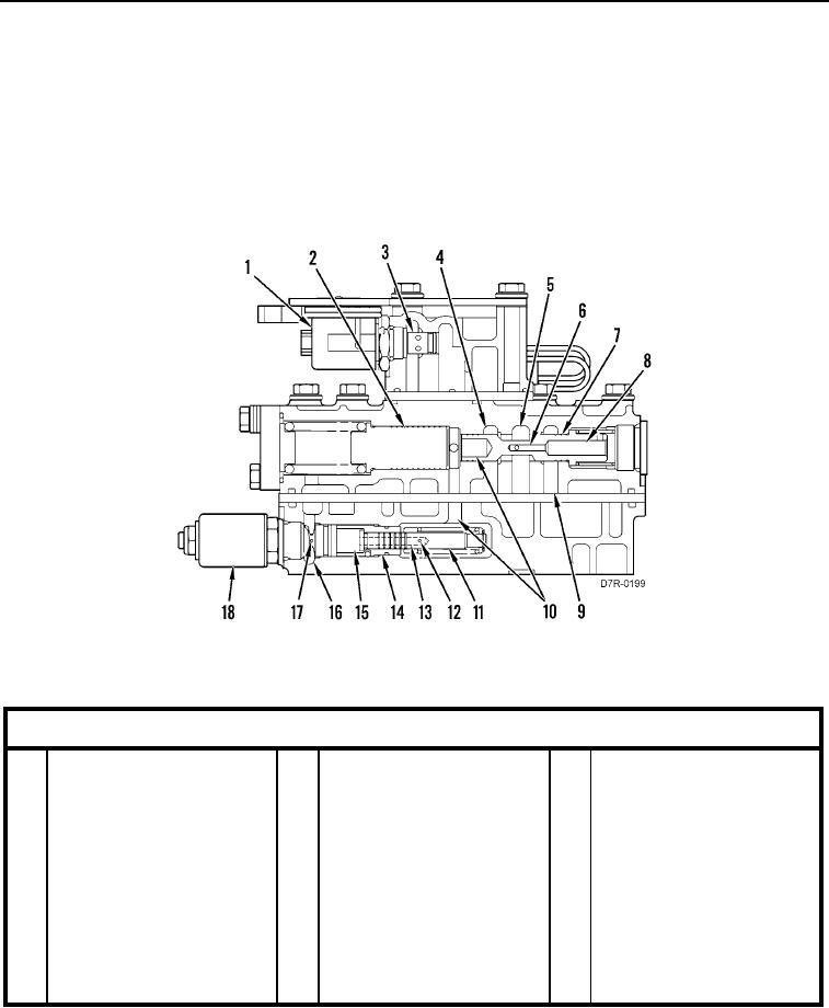
Table 3 identifies the callouts in Figure 16.
Figure 16. Brake Control Valve (Side View of Valve).
0009
Table 3. Brake Control Valve.
0009
Key Component
1
Solenoid to the parking or
7
Reducing spool
13
Passage
secondary brake valve
2
Accumulator piston
8
Chamber for pressure
14
Shutoff valve
feedback
3
Parking and secondary
9
Chamber for supply oil
15
Chamber for pilot pressure
brake valves
4
Drain
10
Chamber for pilot pressure
16
Chamber for drain
5
Brake chamber
11
Spool
17
Pilot valve
6
Passage
12
Drilled hole
18
Proportional solenoid valve