10
TM 5-2410-241-23-1
FIELD MAINTENANCE
-
THEORY OF OPERATION: FINAL DRIVE AND UNDERCARRIAGE
0010
FINAL DRIVE SYSTEM
00010
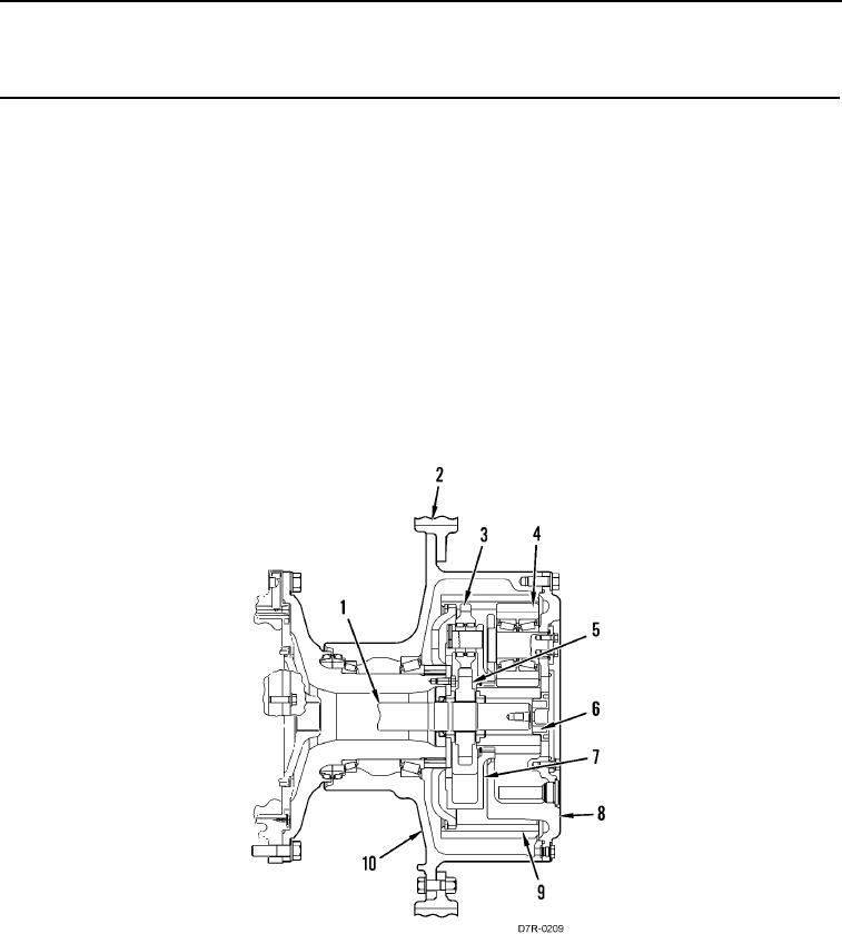
Outer axle shaft (Figure 1, Item 1) sends power to the final drive. Inner sun gear (Figure 1, Item 5) is fastened by
splines to outer axle shaft (Figure 1, Item 1). The rotation of the axle shaft and inner sun gear (Figure 1, Item 5)
turns inner planetary gears (Figure 1, Item 3). Ring gear (Figure 1, Item 9) is a stationary component and inner
planetary gears (Figure 1, Item 3) rotate around the inside of the ring gear (Figure 1, Item 9).
The rotation of inner planetary gears (Figure 1, Item 3) around the inside of the ring gear (Figure 1, Item 9) turns
the inner carrier (Figure 1, Item 7), which is connected to outer sun gear (Figure 1, Item 6) by splines. The rotation
of inner carrier (Figure 1, Item 7) and outer sun gear (Figure 1, Item 6) causes the outer planetary gears (Figure 1,
Item 4) to turn.
The rotation of outer planetary gears (Figure 1, Item 4) around the inside of ring gear (Figure 1, Item 9) turns outer
carrier (Figure 1, Item 8), which is fastened to hub (Figure 1, Item 10). The rotation of hub (Figure 1, Item 10) sends
power to sprocket segments (Figure 1, Item 2) and the track.
The oil level in the final drives is maintained through a filler plug. All components receive splash lubrication oil as
the gears move. The gears throw oil on all of the components.
Figure 1. Final Drives.
0010

