
TM 5-2410-241-23-1
0010
FINAL DRIVE AND UNDERCARRIAGE CONTINUED
Track Roller Frame
00010
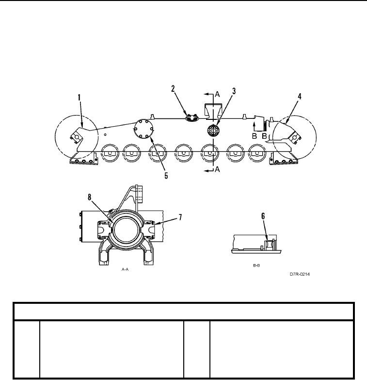
The track roller frame can be separated into two sections. Front roller frame has a large tube assembly. The tube
assembly slides into rear roller frame. Tube contains a recoil spring and track adjustment valves. A groove is
machined in the outer diameter of the tube. Guide assemblies are installed in rear roller frame. The guides are
aligned with the groove. The guides will prevent any rotation of tube inside the rear roller frame.
Figure 6. Track Roller.
0010
Key Components
1
Rear Track Roller Frame
5
Pivot Shaft
2
Track Adjuster Cover
6
Seal
3
Guide Assembly
7
Guide Assembly
4
Front Track Roller Frame
8
Recoil Group