TM 5-2410-241-23-1
0010
FINAL DRIVE AND UNDERCARRIAGE
00010
Pivot Shaft
00010
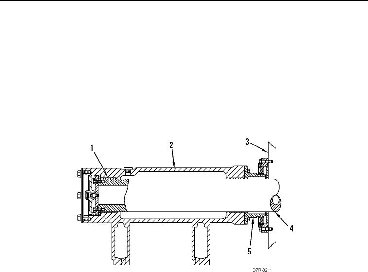
The pivot shaft (Figure 3, Item 4) connects the machine frame (Figure 3, Item 3) with the two track frames
(Figure 3, Item 2). Each track roller frame can rotate about the pivot shaft.
The pivot shaft (Figure 3, Item 4) extends through the pivot shaft cavity in the machine frame (Figure 3, Item 3).
Two sleeve bearings in the machine frame (Figure 3, Item 3) support the machine on the pivot shaft (Figure 3,
Item 4). The pivot shaft (Figure 3, Item 4) is supported by two bearings (Figure 3, Item 1) in the track roller frame
(Figure 3, Item 2).
The track roller frame (Figure 3, Item 2) is filled with oil in order to lubricate the pivot shaft bearings in the track
roller frame (Figure 3, Item 2). The seal (Figure 3, Item 5) contains the oil in the cavity on the track roller frame
(Figure 3, Item 2) and in the pivot shaft cavity.
Figure 3. One Side of Pivot Shaft.
0010

