
TM 5-2410-241-23-1
0010
FINAL DRIVE AND UNDERCARRIAGE CONTINUED
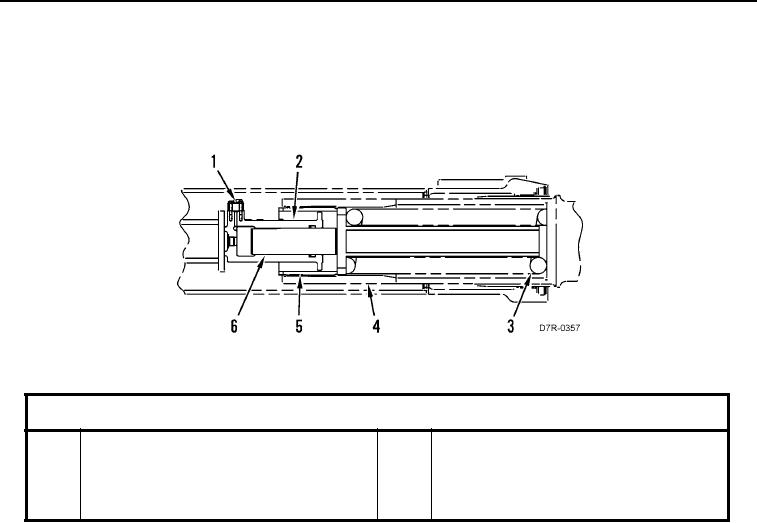
Track adjustment valves are used for moving front roller frame to adjust the track tension. Grease is pumped into
the filler valve causing the piston to move to the right. This causes the front track roller to move out of the rear roller
frame. The movement of the recoil rod and the front idler tightens the track. The tension on the track is released by
a relief valve.
Figure 7. Recoil Group.
0010
Key Components
1
Track Adjustment Valves
4
Tube
2
Cylinder Assembly
5
Nut
3
Recoil Spring
6
Piston