TM 5-2410-241-23-1
0011
IMPLEMENT AND STEERING HYDRAULIC SYSTEM CONTINUED
When an implement circuit is activated, the compensator valve on hydraulic pump senses the load increase from
the signal resolver network causing the pump to upstroke. The pump continues to upstroke until the system
pressure is approximately 305 psi (2,100 kPa) higher than the load signal from the control valve. Pressure limiters
in the implement control valves control the maximum pressure in the implement circuits.
The system pressure will be less than 305 psi (2,100 kPa) higher than the load signal from the control valve under
two circumstances. This lower system pressure occurs when the pump reaches the maximum displacement and
the pump does not achieve the necessary flow. This also occurs when the pressure cutoff setting is reached.
If the steering circuit is activated, the pump upstrokes in the same manner. However, pressure in the steering
circuit is controlled by the cutoff spool in the pump compensator valve. When the steering circuit pressure reaches
an approximate pressure of 5585 psi (38,500 kPa), the pump destrokes enough to maintain the pressure until the
system pressure decreases.
The main relief valve is located on the inlet manifold at the bottom of the valve stack. It limits the pressure
increases (spikes) to approximately 6,100 psi (42,580 kPa).
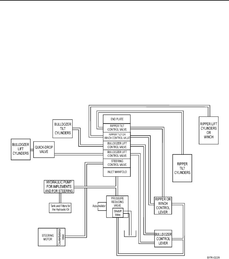
Figure 2. Components of the Hydraulic System.
0011

