
TM 5-2410-241-23-1
0011
IMPLEMENT AND STEERING HYDRAULIC SYSTEM CONTINUED
An open loop hydraulic system is used for steering. The operator uses the steering control lever to initiate a turn.
The steering control lever (Figure 3, Item 1) is mechanically connected to the steering control valve, which is part
of the valve stack.
Figure 3. Steering Control Lever.
0011
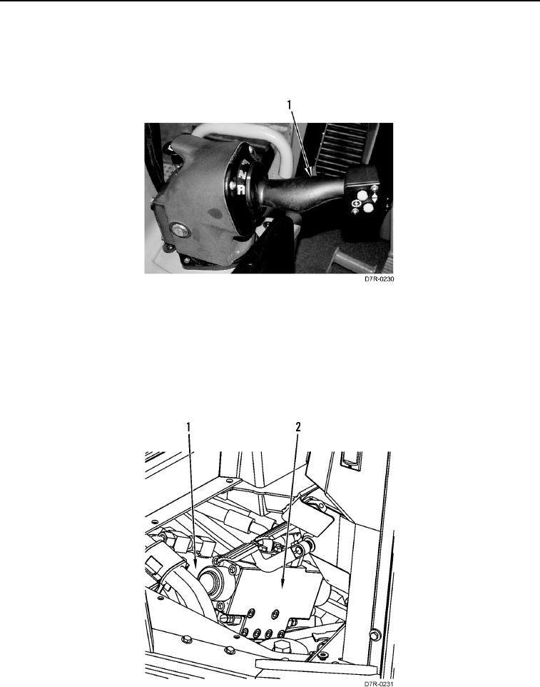
The steering control valve directs oil to the steering motor (Figure 4, Item 1) which is a fixed displacement motor,
and drives the steering differential gears. Power is transferred from one track to the other track during the steering
operation. This allows an efficient application of power to the ground.
The counterbalance valve (Figure 4, Item 2) is attached to the steering motor and controls the speed of steering
motor so that additional torque from the transmission and from the tracks does not drive the motor beyond the
control of the operator.
Figure 4. Counterbalance Valve And Steering Motor.
0011