TM 5-2410-241-23-1
0011
IMPLEMENT AND STEERING HYDRAULIC SYSTEM CONTINUED
When the pilot control lever is moved to an operating position, the pilot supply oil instructs the implement control
valve to send oil to the cylinder.
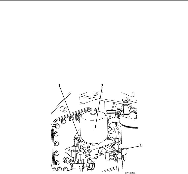
A manifold and reducing valve (Figure 6, Item 3) supplies pilot oil to the control valves for the bulldozer blade and
the implements. The manifold and reducing valve includes a pressure reducing valve, a screen, a relief valve, a
check valve, and an attached accumulator (Figure 6, Item 2). The accumulator and the check valve are used to
maintain supply pressure during momentary drops in system pressure and for a short time after the engine is shut
off.
A shutoff valve (Figure 6, Item 1) is located in the manifold of the pressure reducing valve. A solenoid operates the
shutoff valve that is in the manifold and is energized when the hydraulic lockout switch is activated. When the
solenoid valve is energized, pilot supply oil from the pressure reducing valve enters the shutoff valve of the
manifold. In the LOCK position, the line from the pressure reducing valve is blocked and the oil is diverted to the
tank line. This allows the oil from the pilot control valves to drain to the hydraulic tank. When the hydraulic lockout
switch is toggled to the LOCK position, the solenoid valve is de-energized and spring force moves the shutoff valve
to the LOCK position. When this occurs, a lamp on the instrument panel is activated.
Figure 6. Solenoid for the Shutoff Valve.
0011

