
TM 5-2410-241-23-1
0010
FINAL DRIVE AND UNDERCARRIAGE CONTINUED
Track Roller
00010
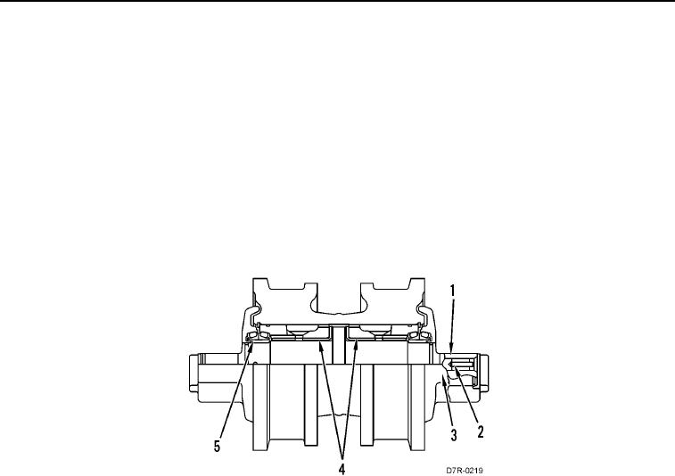
Both single and double flange track rollers are located on each side of the machine. The track rollers are fastened
to the bottom section of the track roller frame and are in contact with the rails on the track links. The flanges on the
track rollers prevent the lateral movement of the track links. A bushing (Figure 11, Item 4) puts the side load on the
roller. The amount of lateral movement or end clearance of the shaft cannot be adjusted.
Duo-Cone seals (Figure 11, Item 5) are attached to both of the ends of shaft (Figure 11, Item 1).
Track Roller Lubrication
00010
The roller is lubricated with the oil in a center passage (Figure 11, Item 3).
Oil is added through shaft (Figure 11, Item 1) at a stopper (Figure 11, Item 2) and forced through the center
passage (Figure 11, Item 3) to the lubrication holes in shaft (Figure 11, Item 1). Duo-Cone seals (Figure 11, Item 5)
seal the oil in the roller at each end.
Figure 11. Track Roller (Double Flange).
0010
END OF WORK PACKAGE