
TM 5-2410-241-23-1
0010
FINAL DRIVE AND UNDERCARRIAGE CONTINUED
Master Link
00010
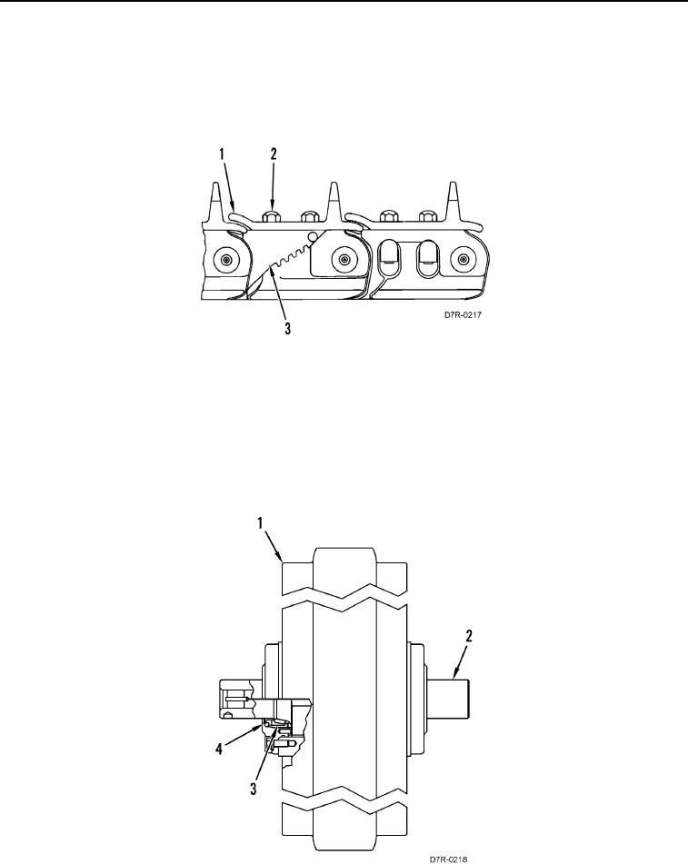
Two-piece master links (Figure 9, Item 3) and a master shoe (Figure 9, Item 1) are bolted together (Figure 9,
Item 2). Each assembled track link is sealed. Independent lubrication is provided for components. The seals and
the lubrication oil help to prevent internal wear on the track joints. Significant wear occurs only on the outside of the
bushings and on the outside of the track links.
Figure 9. Master Links and Master Shoe.
0010
Track Idler
00010
The machine has a front and a rear idler for each roller frame.
Stabilizer (Figure 10, Item 3) controls the position of seal (Figure 10, Item 4). The amount of side movement or end
clearance of the shaft cannot be adjusted.
Each idler (Figure 10, Item 1) has Duo-Cone seals (Figure 10, Item 4) at both ends of shaft (Figure 10, Item 2).
The center of shaft (Figure 10, Item 2) is an oil reservoir. The oil is used for lubrication of the bearing surfaces.
Figure 10. Idlers.
0010