TM 5-2410-241-23-1
0010
FINAL DRIVE AND UNDERCARRIAGE CONTINUED
Sealed and Lubricated Track
00010
The track that is standard on this machine is sealed and lubricated. Each track assembly has links, pins, bushings,
thrust rings, polyurethane seal assemblies, rubber stoppers, and polyurethane plugs.
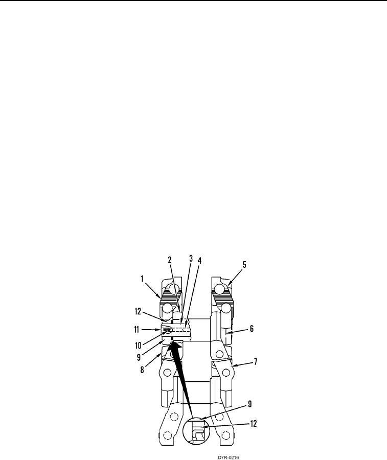
Each of the track links (Figure 8, Items 1 and 5) fits over the preceding track link. Link (Figure 8, Item 1) fits over
link (Figure 8, Item 8). Link (Figure 8, Item 5) fits over link (Figure 8, Item 7). The connection of the track links make
the track assembly.
Each track link is designed with a counterbore in the end in order to fit over the preceding track link. Seals
(Figure 8, Item 12) are installed in the counterbores. Each seal includes a load ring and a seal ring. The load ring
pushes the seal ring against the end of bushing (Figure 8, Item 2) and against the link counterbore. The seal ring
makes a positive seal between the bushing and the link counterbore.
Thrust rings (Figure 8, Item 9) are installed on pin (Figure 8, Item 6). The thrust rings compress the seals to a
specific tolerance. The thrust rings also control the end play (free movement) of the track joint. The seals and the
thrust rings keep foreign materials out of the track joint. The seals and the thrust rings keep lubricating oil in the
track joint.
Each pin (Figure 8, Item 6) is designed with an oil reservoir (Figure 8, Item 4), which runs most of the length of the
axis of the pin. A radial hole (Figure 8, Item 3) is drilled in the middle of the length of the pin, which directs oil to the
surface between pin (Figure 8, Item 6) and bushing (Figure 8, Item 2) and to the lips of the seal rings.
The pin, the bushing, and the lips of the seal rings are lubricated in order to prevent wear.
The oil is kept in the pin by stopper (Figure 8, Item 11) and by plug (Figure 8, Item 10). The pin is filled with oil
through a hole in the center of stopper (Figure 8, Item 11). When the chamber in the pin is filled, a plug (Figure 8,
Item 10) is installed in stopper (Figure 8, Item 11).
Figure 8. Track Assembly.
0010

