
TM 5-2410-241-23-1
0011
IMPLEMENT AND STEERING HYDRAULIC SYSTEM CONTINUED
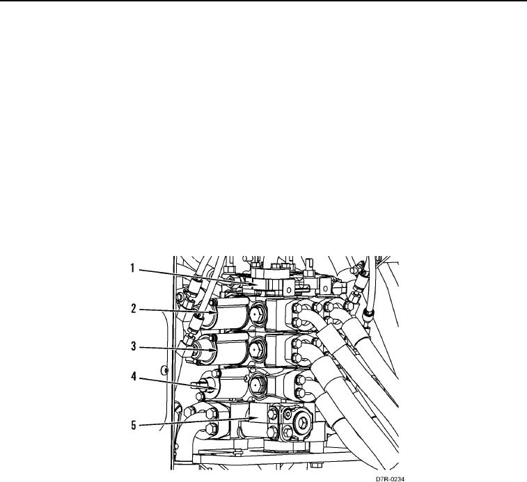
The valve stack has an inlet manifold (Figure 7, Item 5) and an end cover (Figure 7, Item 1) and can have as many
as five control sections. The implement control valves are in parallel with each other.
The steering control valve (Figure 7, Item 4) is controlled by a mechanical linkage from the steering control lever.
The steering control valve has priority over the implement control valves. This means that no less than half of the
steering speed is available at all times.
The steering control has three positions: STEER RIGHT, HOLD, and STEER LEFT.
The control valves for the bulldozer, the ripper (if equipped) and winch (if equipped) are controlled by the pilot
control system. The implement and steering hydraulic system bulldozer blade lift control valve (Figure 7, Item 3)
has four positions: RAISE, HOLD, LOWER, and FLOAT.
The bulldozer tilt control valve (Figure 7, Item 2) has three positions: TILT RIGHT, HOLD, and TILT LEFT.
The ripper lift control valve has three positions: RAISE, HOLD, and LOWER.
The ripper tip control valve has three positions: TIP OUT, HOLD, and TIP IN.
The winch control valve has three positions: REEL IN, HOLD, and REEL OUT.
Figure 7. Valve Stack for Machine without Ripper.
0011