
TM 5-2410-241-23-1
0011
IMPLEMENT AND STEERING HYDRAULIC SYSTEM CONTINUED
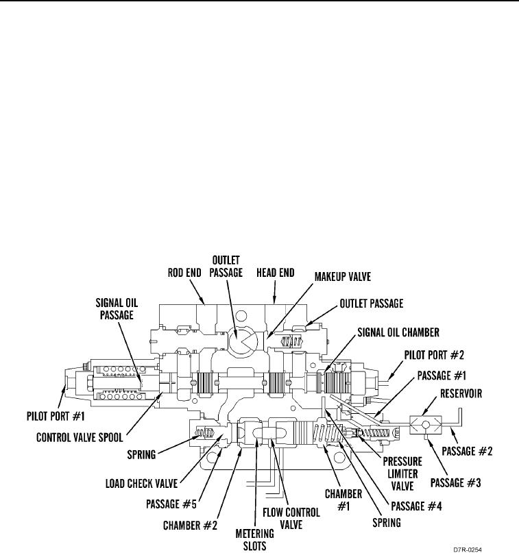
When the signal oil pressure in spring chamber #1 reaches approximately 3,300 psi (22,750 kPa), the spool in
pressure limiter valve moves from the valve seat. Oil is sent through the outlet passage to the tank.
The signal oil causes the flow control valve to move to the right. The flow of pump oil to the lift circuit decreases
until the pressure of the cylinder oil decreases.
c. Load Check Valve
00011
The load check valve prevents reverse oil flow from the lift cylinders which can cause cylinder drift or load loss. The
load check valve will not open until pump oil pressure in chamber #2 creates a force against the load check valve
that is higher than the opposing force against the other side of the check valve. The opposing force is the sum of
the force of the spring and the force that is created by the oil pressure in passage.
d. Makeup Valve
00011
Makeup valve is in the head end of the lift circuit.The makeup valve opens when cylinder oil pressure in head end
passage drops approximately 2 psi (14 kPa) below the return oil pressure in the outlet passage. Makeup valve
adds return oil in the outlet passage to cylinder oil in head end passage. The additional oil prevents cavitation
(vacuum) in the lift cylinders.
Figure 26. Bulldozer Lift Control Valve (General Information).
0011