
TM 5-2410-241-23-1
0011
IMPLEMENT AND STEERING HYDRAULIC SYSTEM CONTINUED
Basic Valve Operation
00011
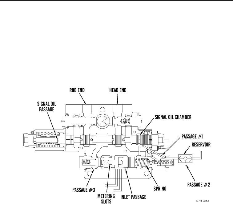
a. Bulldozer Lift Control Valve (Hold)
00011
When the control valve spools, all of the implement/attachment valve spools, and the steering valve spools are in
the HOLD position, pump oil through the steering control valve flows to the inlet passage. Oil flows around the flow
control valve and into the metering slots which moves the flow control valve against the spring. This valve
movement allows all the oil flow through the inlet passage to flow to the next control valve. Because all the valve
spools are in the HOLD position, pump oil fills the parallel oil passage of the control valves.
The pump maintains the pressure at approximately 525 psi (3,600 kPa). Signal oil passage, chamber, passage #1,
resolver, and passage #2 are drained. The oil that is in the rod end passage, head end passage, and passage #3 is
blocked.
Figure 27. Bulldozer Lift Control Valve (HOLD).
0011